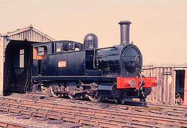
A look at the construction of the NLR 0-6-0T, some of which were transferred from London to the Midlands in LMS days.
The pitfalls and mitigation of errors when building loco kits where two manufacturers produce major components.
The most recent build project I have undertaken is eventually going to grace my layout, Carlsby LMS. I chose this model at this time because on the surface it appeared to be the most complete set of parts "in one box" that I had bought a couple of years ago and that would therefore not need too many extras during the lockdown we are in. The kit is that of GEM's North London Railway's 0-6-0T with all ancillary parts in several bags,bought through GEM but made by BRANCHLINES specifically for the GEM kit. (Photo of No. 58850 at the Bluebell could perhaps go here). The kit is nicely presented in a clear plastic box which will serve well later for storage. There a re three lots of instruction in the box, Body (GEM), External Pipework on the body again GEM ( there is a lot of external pipework on the prototype) and finally the Chassis has a set of instructions covering three sheets but without a diagram of the nickel silver fret from which the chassis is formed. Therefore the first task is to identify the parts since the instruction sheet only gives you a series of process numbers, not part numbers!
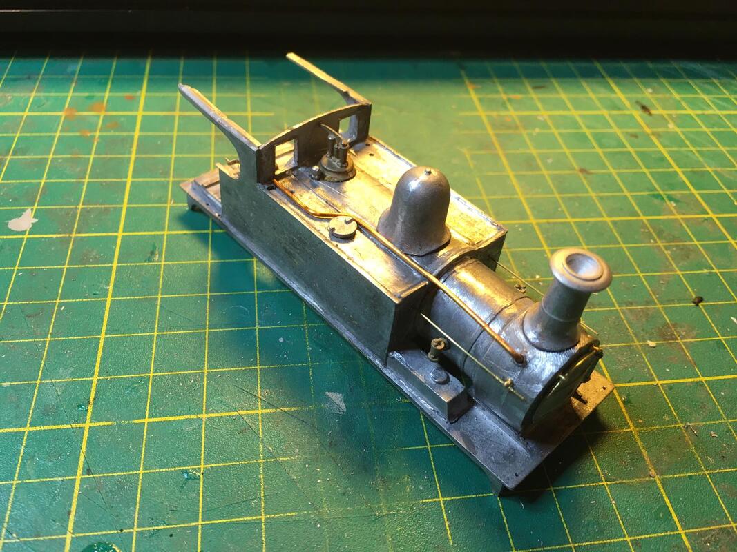
The Body instructions first constructional words are "make the chassis first". This is not unusual in kits which include a chassis and therefore those plans and all the white metal body parts were put aside for later. The chassis fret is in actuality quite simple once the EM and P4 parts are discounted along with such things as wooden brake hangers etc., which were modified out of the prototype before my modelling era. The construction of the frames needed to be looked at carefully because the spacers did not make the unit square as they should have done making an early intervention to create a square set of frames. It was stated in the instructions that the motor if fitted conventionally backwards from and above the centre axle it would protrude into the cab, making the fitting of a detailed backhead impossible. The answer was to undersling the worm with the moter pointing upwards and slightly forwards into the tank. At first sight this seemed a sensible process although new to me. The next "snag" appeared when I tried fitting the wheelsto the axles in order to check the chassis for it's accuracy. all three Romford axles would not accept a wheel at one end!! I have built many locos using these axles and have never come across this problem before, the threaded section was too short for the retaining nut to engage. Were these axles seconds I wondered? Luckily another kit had three suitable replacements. i have since acquired new ones from Markits but didn' have the nerve to tackle Mark about the faulty ones, he can be very acerbic when criticised.. So now I had a freely rolling basic chassis the next thing was to form and attach the cylinders. The fret does not include the ends, therefore the body parts must be searched for white metal end covers and the first use of epoxy is required because careful positioning of the slide bars is vital.The cylinders are bolted to the chassis, a feature which would become a lifeline later. At this stage it became clear that clearance of the rod cranks fixings would be very close. Thinning of the rod ends and the securing circlips was carried out to the best of my ability but the necessary clearance could still not be achieved with the slide bars parallel to the frames. there is not part provided to brace the rear end of the slide bars so I made the decision t make a cross member to go across the top of the frames bent downwards at the ends and soldered to the slide bar ends. this was made of such a length across the frames that the slide bars were angled quite disinctly outwards at the rear in order for the cranks to clear the crosshead on both forward and rear passes. Not the prettiest solution but I figured that once the footplate was fitted it would be less noticeable. After free running the chassis in this state it was found to work but somewhat stiffer than I would have liked. I have experienced chassis that have become less sluggish once run in so consoled myself with that thought when I fitted the motor and wired it up to the pickups. The ensemble ran both sluggishly and hesitantly, an altogether disappointing result for the best part of three weeks work. This could not be the way it was meant to be, so back to the instructions. There was no help from the BRANCHLINES paperwork. However on going further into the GEM body instructions I found an interesting reference to the centre to centre measurements for the cylinders! So out with the calipers and I find that my c to c is nearly 2mm less than the GEM figure. Why is there no mention of this in the BRANCHLINES guide? Why is this figure not Highlighted early on in the GEM notes. How am I to rectify this gross shortcoming. Thank goodness for the cylinders being bolted to the frames!!. Undo the bolts alittle and slide in a suitable piece of plasticard , re-tighten the bolts and we have already reduced the splay at the rear of the slidebars and provided good clearance at the front as well as at the rear. The crossmember bracing the rear of the slide bars was removed and made a similar bit shorter to the amount the front had been widened and I now have parallel slidebars and bingo! A fairly free running, complete, chassis. After all this I found that the motor fouls the top of the tank section of the body and have now had to shave both the motor and the inside of the tank top to allow clearance. To be fair I could have angled the motor a little more and maybe achieved the same clearance but I felt I had taken enough liberties with the chassis.
It goes without saying that I "should have read the instructions completely before starting on anything". Call me a typical male! However there are no figures given anywhere in any of the instructions for the modeller working in EM or P4. It has shown me, not for the first time, that building kits which have been around for years and that you would have thought had had all the wrinkles ironed out by now is not as straightforward as it should be, after all we pay a lot of money for them and they should have clearer, less ambiguous instructions and processes. Somebody at the manufacturers must have tried them out - mustn't they?
Now for the body! Where are the two buffer beams? and do we have two right hand sandboxes? and where is the second ejector?To all three questions there is a disappointing answer!!!! By this time I'm in a somewhat dark mood. These people need some form of quality control! An irate E-mail to GEM got a quick reply with a promise of an "as soon as possible" reparation - 2 weeks later a further prod got an "it's being posted" response. Some 3 weeks after the first E-mail the parts duly arrived and the body progressed to it's completion bar painting.
When tested on my layout the loco proved to be the noisiest unit I have ever made. I worked on the assumption that this was to do with the meshing of worm and axle pinion being too tight. There was not much room for manoeuvre by way of moving the worm away from the pinion because the motor mount is a fixed unit. A little filing of the worm and pinion did nothing to lessen the problem. A new approach was required if this loco was not to be a head turner for the wrong reasons. A totally new mount and gears from Markits and rejigging the motor into a more conventional position laying forwards into the boiler proved to be satisfactory with only a little reduction of the lower part of the firebox backhead required to make it fit. The loco is now complete and runs a lot better than it did with the original motor/gearbox combination and while still a little noisy it has still to be fully "run in".
The most recent build project I have undertaken is eventually going to grace my layout, Carlsby LMS. I chose this model at this time because on the surface it appeared to be the most complete set of parts "in one box" that I had bought a couple of years ago and that would therefore not need too many extras during the lockdown we are in. The kit is that of GEM's North London Railway's 0-6-0T with all ancillary parts in several bags,bought through GEM but made by BRANCHLINES specifically for the GEM kit. (Photo of No. 58850 at the Bluebell could perhaps go here). The kit is nicely presented in a clear plastic box which will serve well later for storage. There a re three lots of instruction in the box, Body (GEM), External Pipework on the body again GEM ( there is a lot of external pipework on the prototype) and finally the Chassis has a set of instructions covering three sheets but without a diagram of the nickel silver fret from which the chassis is formed. Therefore the first task is to identify the parts since the instruction sheet only gives you a series of process numbers, not part numbers!
The Body instructions first constructional words are "make the chassis first". This is not unusual in kits which include a chassis and therefore those plans and all the white metal body parts were put aside for later. The chassis fret is in actuality quite simple once the EM and P4 parts are discounted along with such things as wooden brake hangers etc., which were modified out of the prototype before my modelling era. The construction of the frames needed to be looked at carefully because the spacers did not make the unit square as they should have done making an early intervention to create a square set of frames. It was stated in the instructions that the motor if fitted conventionally backwards from and above the centre axle it would protrude into the cab, making the fitting of a detailed backhead impossible. The answer was to undersling the worm with the moter pointing upwards and slightly forwards into the tank. At first sight this seemed a sensible process although new to me. The next "snag" appeared when I tried fitting the wheelsto the axles in order to check the chassis for it's accuracy. all three Romford axles would not accept a wheel at one end!! I have built many locos using these axles and have never come across this problem before, the threaded section was too short for the retaining nut to engage. Were these axles seconds I wondered? Luckily another kit had three suitable replacements. i have since acquired new ones from Markits but didn' have the nerve to tackle Mark about the faulty ones, he can be very acerbic when criticised.. So now I had a freely rolling basic chassis the next thing was to form and attach the cylinders. The fret does not include the ends, therefore the body parts must be searched for white metal end covers and the first use of epoxy is required because careful positioning of the slide bars is vital.The cylinders are bolted to the chassis, a feature which would become a lifeline later. At this stage it became clear that clearance of the rod cranks fixings would be very close. Thinning of the rod ends and the securing circlips was carried out to the best of my ability but the necessary clearance could still not be achieved with the slide bars parallel to the frames. there is not part provided to brace the rear end of the slide bars so I made the decision t make a cross member to go across the top of the frames bent downwards at the ends and soldered to the slide bar ends. this was made of such a length across the frames that the slide bars were angled quite disinctly outwards at the rear in order for the cranks to clear the crosshead on both forward and rear passes. Not the prettiest solution but I figured that once the footplate was fitted it would be less noticeable. After free running the chassis in this state it was found to work but somewhat stiffer than I would have liked. I have experienced chassis that have become less sluggish once run in so consoled myself with that thought when I fitted the motor and wired it up to the pickups. The ensemble ran both sluggishly and hesitantly, an altogether disappointing result for the best part of three weeks work. This could not be the way it was meant to be, so back to the instructions. There was no help from the BRANCHLINES paperwork. However on going further into the GEM body instructions I found an interesting reference to the centre to centre measurements for the cylinders! So out with the calipers and I find that my c to c is nearly 2mm less than the GEM figure. Why is there no mention of this in the BRANCHLINES guide? Why is this figure not Highlighted early on in the GEM notes. How am I to rectify this gross shortcoming. Thank goodness for the cylinders being bolted to the frames!!. Undo the bolts alittle and slide in a suitable piece of plasticard , re-tighten the bolts and we have already reduced the splay at the rear of the slidebars and provided good clearance at the front as well as at the rear. The crossmember bracing the rear of the slide bars was removed and made a similar bit shorter to the amount the front had been widened and I now have parallel slidebars and bingo! A fairly free running, complete, chassis. After all this I found that the motor fouls the top of the tank section of the body and have now had to shave both the motor and the inside of the tank top to allow clearance. To be fair I could have angled the motor a little more and maybe achieved the same clearance but I felt I had taken enough liberties with the chassis.
It goes without saying that I "should have read the instructions completely before starting on anything". Call me a typical male! However there are no figures given anywhere in any of the instructions for the modeller working in EM or P4. It has shown me, not for the first time, that building kits which have been around for years and that you would have thought had had all the wrinkles ironed out by now is not as straightforward as it should be, after all we pay a lot of money for them and they should have clearer, less ambiguous instructions and processes. Somebody at the manufacturers must have tried them out - mustn't they?
Now for the body! Where are the two buffer beams? and do we have two right hand sandboxes? and where is the second ejector?To all three questions there is a disappointing answer!!!! By this time I'm in a somewhat dark mood. These people need some form of quality control! An irate E-mail to GEM got a quick reply with a promise of an "as soon as possible" reparation - 2 weeks later a further prod got an "it's being posted" response. Some 3 weeks after the first E-mail the parts duly arrived and the body progressed to it's completion bar painting.
When tested on my layout the loco proved to be the noisiest unit I have ever made. I worked on the assumption that this was to do with the meshing of worm and axle pinion being too tight. There was not much room for manoeuvre by way of moving the worm away from the pinion because the motor mount is a fixed unit. A little filing of the worm and pinion did nothing to lessen the problem. A new approach was required if this loco was not to be a head turner for the wrong reasons. A totally new mount and gears from Markits and rejigging the motor into a more conventional position laying forwards into the boiler proved to be satisfactory with only a little reduction of the lower part of the firebox backhead required to make it fit. The loco is now complete and runs a lot better than it did with the original motor/gearbox combination and while still a little noisy it has still to be fully "run in".
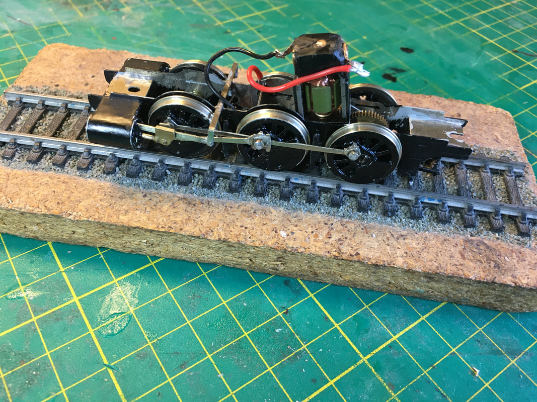
The first of three views of the NLR tank's chassis.
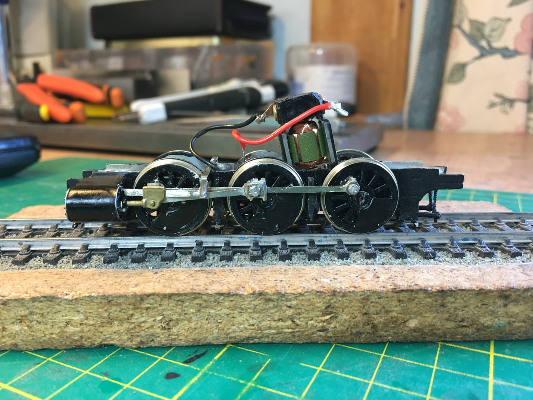
A side view at track level.
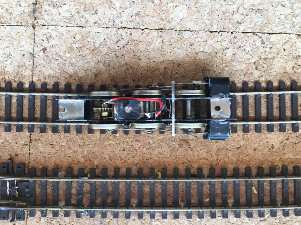
A birds eye view showing the cylinders and crosshead arrangement.
The next few pictures show the construction of the body.
A general view of the loco body taking shape.
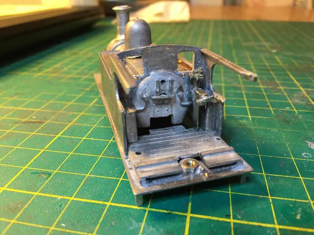
A view of the cab area and firebox backhead.
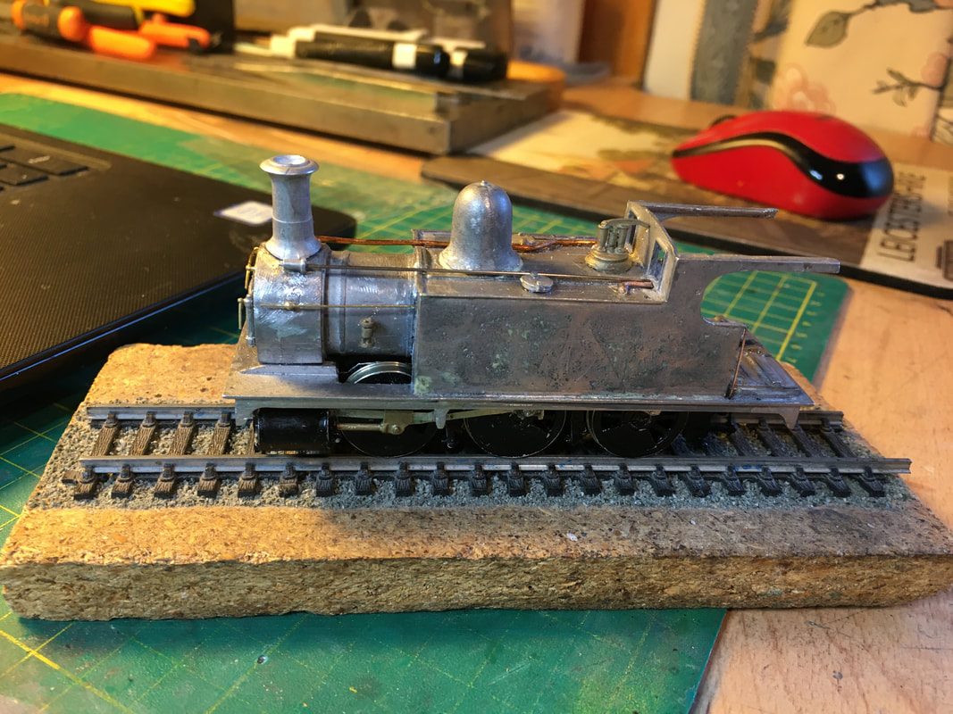
The body and chassis are brought togther for a test fitting. Behind the loco can be spotted a rare LMS liveried wireless mouse!
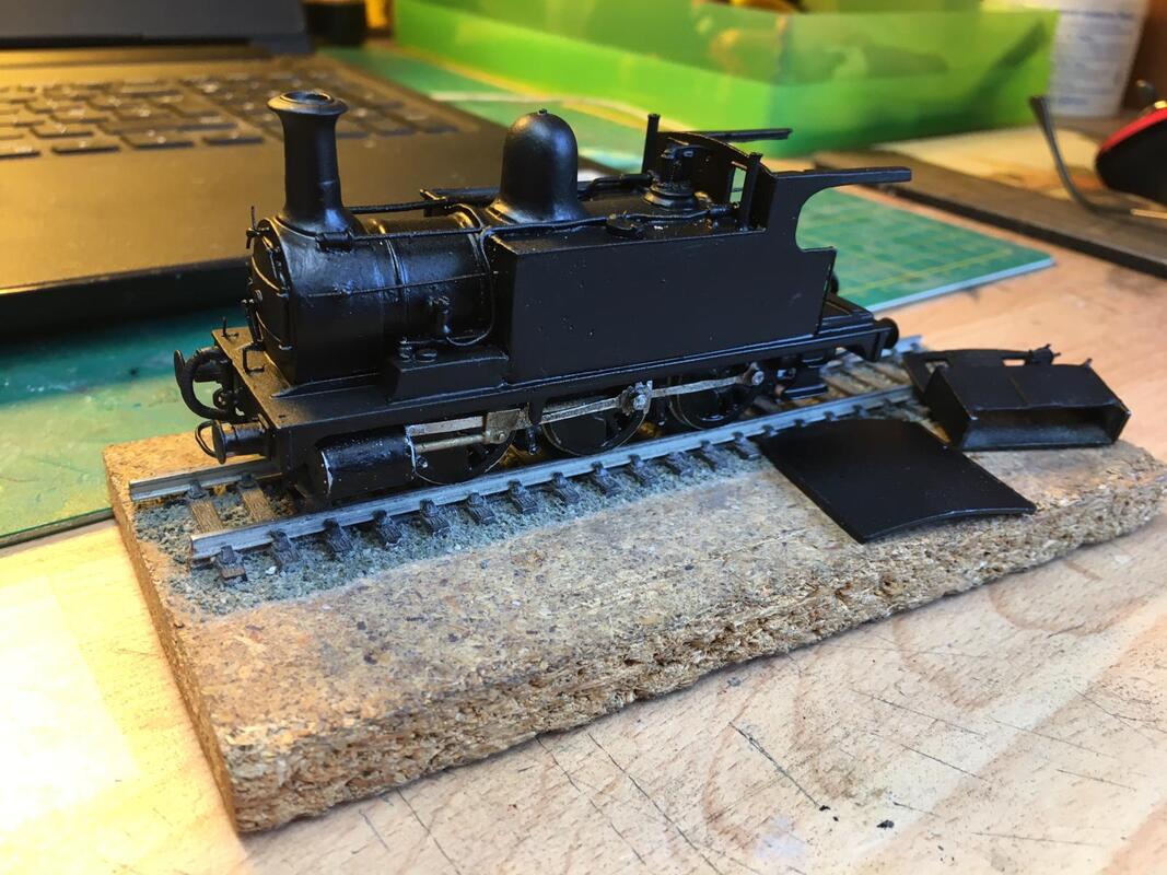
What a difference a coat of paint makes. The loco body and chassis together with the cab roof and bunker assembly.
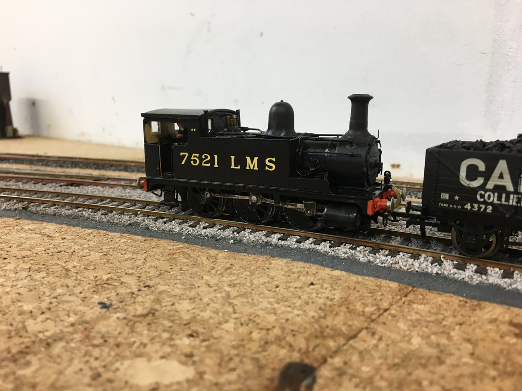
The finished product. Painted and decals added, the loco can be seen on Carlsby on a test run.
